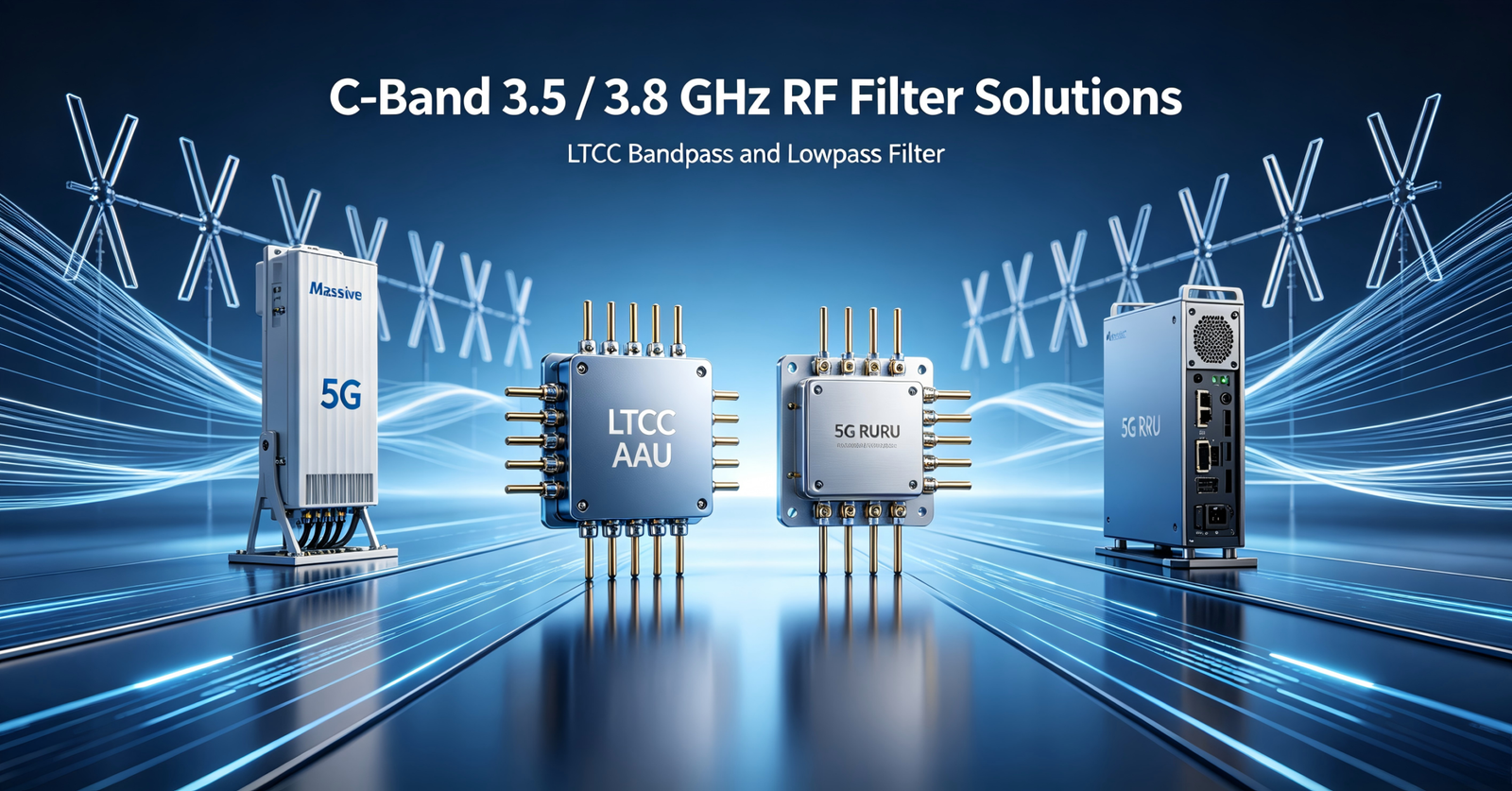
LTCC Bandpass and Lowpass Filter Selection Reference for 5G AAU, RRU, Massive MIMO, and Compact RF Front-End Designs
The 3.5 / 3.8 GHz C-Band range is critical for 5G mid-band deployments and is widely used in macro base station AAUs, outdoor RRUs, small cells, private 5G networks, Massive MIMO systems, and compact RF front-end modules.
In C-Band transmit and receive paths, the core task of RF filters is to achieve precise frequency management: allowing the target operating band to pass with low insertion loss while suppressing adjacent-channel interference, out-of-band spurs, high-frequency harmonics, and blocker signals. C-Band bandpass filters and lowpass filters play distinct but complementary roles, working together to deliver cleaner and more stable spectrum performance for the system.
This application note focuses on 3.5 / 3.8 GHz C-Band RF front-end applications in 5G base stations. It explains the roles of LTCC bandpass and lowpass filters in transmit paths, receive paths, and PA-output harmonic suppression, and provides preliminary selection references for AAUs, RRUs, Massive MIMO systems, small cells, and C-Band RF modules.
Quick Selection Guide
The following models can be used as a preliminary selection reference for 3.5 / 3.8 GHz C-Band 5G base station RF front ends. Final selection should be verified against the target frequency band, insertion loss, return loss, stopband rejection, power level, PCB layout, thermal conditions, and S-parameter measurements.
C-Band Bandpass Filter Quick Selection
| Model | Passband | Center Frequency (MHz) | Max. IL @ 25°C (dB) | Typ. VSWR | Stopband Rejection | Power (W) | Package | Typical Application |
|---|---|---|---|---|---|---|---|---|
| FBFCN-3600 | 3300–3900 MHz | 3600 | 1.8 | 1.3 | DC–1850 MHz ≥ 20 dB; 5000–8000 MHz ≥ 20 dB | 1.5 | FV1206 | Macro AAU, RRU, Small Cell |
| FBFCV-3641 | 3400–3850 MHz | 3636 | 3.5 | 1.7 | DC–2670 MHz ≥ 26 dB; 2930 MHz @ 20 dB; 4650 MHz @ 20 dB; 5350–9600 MHz ≥ 30 dB | 0.5 | JV1210C-2 | Compact RF Front-End, Massive MIMO |
| FBFCN-3700 | 3000–4600 MHz | 3700 | 3.5 | 2.26 | DC–2100 MHz ≥ 21 dB; 5600–8000 MHz ≥ 24 dB | 2.5 | FV1206-4 | R&D Test Platform, Multi-Band Equipment |
| FBFCV-4085 | 3130–5040 MHz | 4085 | 4.0 | 2.1 | DC–2520 MHz ≥ 15 dB; 6260 MHz @ 17 dB; 6380–8000 MHz ≥ 15 dB; 8000–11000 MHz ≥ 14 dB | 5 | JV1210C | Integrated RF Module, Platform Design |
| FBFCV-3350 | 2570–4130 MHz | 3350 | 3.5 | 2.3 | DC–1900 MHz ≥ 14 dB; 2065 MHz @ 17 dB; 5140–8000 MHz ≥ 20 dB | 4 | JV1210C | Multi-Band Front End, Project Evaluation |
FBFCN-3600 and FBFCV-3641 are recommended as priority evaluation models for standard C-Band 5G base station projects. For projects in the R&D phase or requiring broader mid-band coverage, wideband models such as FBFCN-3700 and FBFCV-4085 can be further evaluated.
The parameters above are intended for quick model comparison only. For complete specifications, including test conditions, power rating, operating temperature range, package dimensions, and S-parameters, please refer to the latest datasheet of each model.
C-Band PA-Output Lowpass Filter Quick Selection
| Model | Passband Freq. (MHz) | 3 dB Cutoff Freq. (MHz) | Max. IL @ 25°C (dB) | Typ. VSWR | Typical Stopband Rejection | Power (W) | Package | Typical Application |
|---|---|---|---|---|---|---|---|---|
| FLFCN-3800 | DC–3900 | 5090 | 1.0 | 1.5 | 6000 MHz ≥ 20 dB; 5700–8300 MHz @ 30 dB; 13000 MHz @ 23 dB | 8 | FV1206 | General C-Band PA Harmonic Suppression |
| FLFCG-3800 | DC–3900 | 4700 | 1.8 | 1.5 | 5800–6200 MHz ≥ 20 dB; 6200–8400 MHz @ 42 dB; 8400–12000 MHz @ 30 dB; 12000–18000 MHz @ 20 dB | 4.5 | GE0805C-2 | Stronger 2nd-Harmonic Suppression |
| FLFTC-4000 | DC–4000 | 5325 | 1.0 Typ. | 1.2 | 7250 MHz @ 20 dB; 9500 MHz @ 20 dB | 10 | FR933 | Supplementary LPF with Good Passband Margin |
| FLFCN-4400 | DC–4400 | 5290 | 1.0 | 1.2 | 6700 MHz ≥ 20 dB; 6280–9800 MHz @ 30 dB; 9800–13000 MHz @ 20 dB | 8 | FV1206 | Wider C-Band / Platform-Based LPF Design |
| FLFCG-4400 | DC–4400 | 5200 | 2.1 | 1.78 | 6200–6700 MHz ≥ 20 dB; 6700–8800 MHz ≥ 45 dB; 8800–12200 MHz @ 33 dB; 12200–18000 MHz @ 20 dB | 4.5 | GE0805C-2 | Wide Passband + Far-Out Harmonic Suppression |
The specifications above are typical device-level values. Actual system-level suppression performance may vary with PCB layout, matching networks, power level, source/load impedance conditions, and test conditions. Appropriate harmonic-suppression margin should be reserved during the design phase. Final selection should be evaluated against the PA output spectrum, system-level transmit specifications, link budget, and compliance requirements.
1. Core Role of C-Band Filters in 5G Base Stations
In C-Band 5G base stations, bandpass filters are essential frequency-selective components. C-Band filter solutions can support n77/n78 5G mid-band applications and meet the high-density layout requirements of AAUs, RRUs, Massive MIMO systems, and compact RF front-end modules.
The C-Band Bandpass Filter is the core frequency-selective component for 3.5 GHz and 3.8 GHz operating band selection. It is mainly used for transmit band selection, receive-path interference rejection, and system-level spectrum management.
Lowpass filters are typically used as supplementary filtering solutions at the PA output stage to suppress second-, third-, and higher-order harmonics.
These two filter types do not replace each other. Instead, they are applied in different positions of the 5G base station RF front end according to the system architecture, RF chain position, and transmit performance requirements.
1.1 Transmit Band Selection
In the transmit chain, C-Band bandpass filters allow target operating bands such as 3300–3900 MHz or 3400–3850 MHz to pass, while suppressing non-target signals on both sides of the operating band. This helps reduce the risk of out-of-band spurious emissions and adjacent-channel interference.
1.2 Receive-Path Interference Rejection
In the receive chain, bandpass filters attenuate strong out-of-band interference from other cellular bands, private network systems, industrial wireless equipment, or nearby base stations, helping protect the LNA and the downstream receive chain.
1.3 System-Level Spectrum Management
For high-density Massive MIMO systems, miniaturized RRUs, and integrated AAUs, filters affect not only RF performance but also PCB footprint, channel-to-channel consistency, thermal design margin, and long-term system stability.
2. Transmit Chain: Coordinated BPF and LPF Filtering Architecture
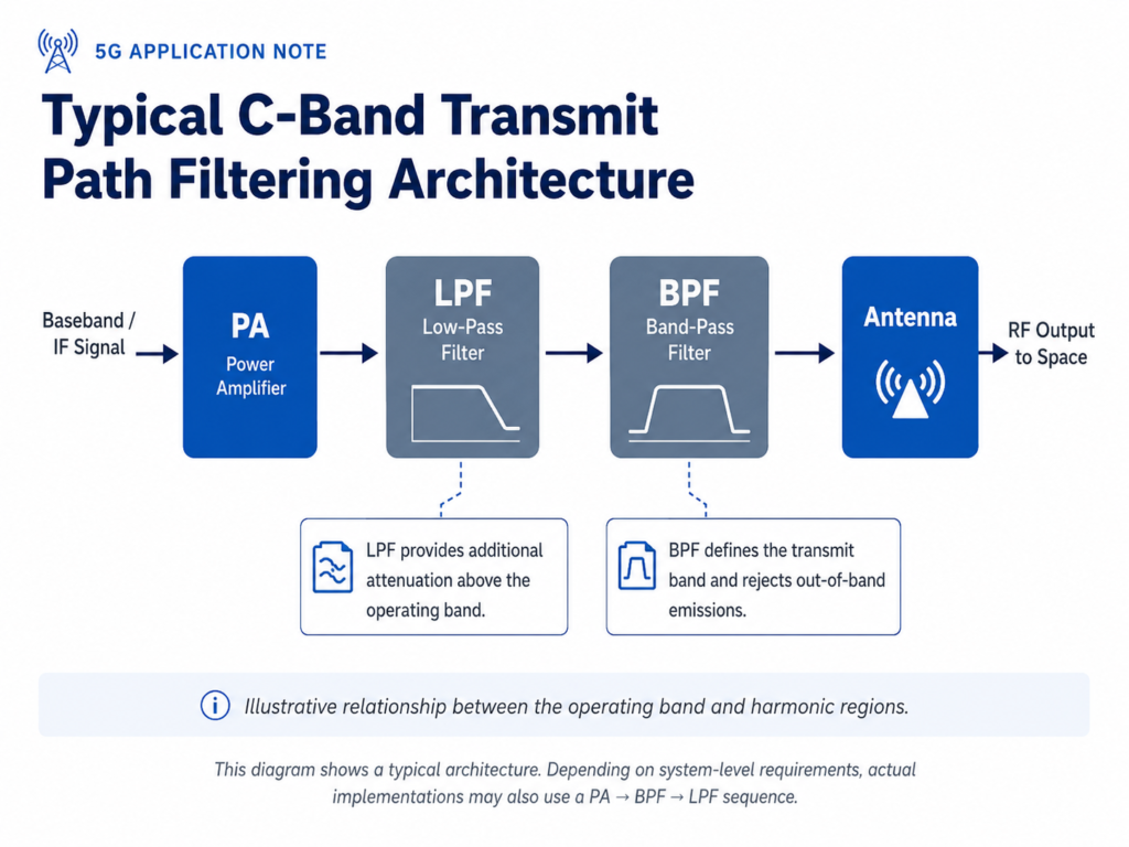
In the 5G base station transmit chain, the power amplifier (PA) output signal may contain not only the target C-Band carrier but also broadband noise, intermodulation products, LO leakage, out-of-band spurious emissions, and second-, third-, and higher-order harmonics generated by PA nonlinearity.
If these unwanted frequency components reach the antenna port without effective attenuation, they may increase the risk of adjacent-channel interference and reduce system-level RF compliance margins. Therefore, an appropriate filtering network is typically configured between the PA output stage and the antenna port, depending on the system architecture.
| Component | Primary Function |
|---|---|
| C-Band Bandpass Filter | Selects the 3.5 / 3.8 GHz operating bands and suppresses near-band adjacent-channel and out-of-band signals. |
| Lowpass Filter | Attenuates second-, third-, and higher-order harmonics above the operating band. |
This coordinated filtering approach is well suited for C-Band 5G base station RF front ends with stringent requirements for transmit spectral purity, adjacent-channel coexistence, and harmonic suppression.
3.Why an LPF May Be Needed in Addition to a BPF
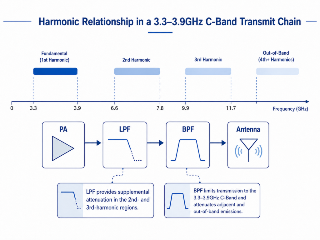
In the C-Band 3.5 / 3.8 GHz transmit chain, PA nonlinearity may generate second-, third-, and higher-order harmonics.
| Operating Band | 2nd Harmonic Range | 3rd Harmonic Range |
|---|---|---|
| 3.3–3.9 GHz | 6.6–7.8 GHz | 9.9–11.7 GHz |
The core function of a C-Band bandpass filter is to ensure low insertion loss and good impedance matching within the operating band, while providing near-band adjacent-channel rejection on both sides of the passband.
For far-out high-frequency harmonics, such as second- and third-order harmonics, a bandpass filter may provide a certain degree of attenuation. However, whether this attenuation is sufficient depends on the specific filter model, PA output spectrum, system power level, PCB layout, and system-level emission requirements.
Therefore, cascading a lowpass filter at the PA output stage is typically an effective architectural choice to provide supplementary attenuation for these far-out high-frequency harmonics.
The harmonic attenuation performance of an LPF depends on the harmonic frequencies, the LPF’s stopband rejection capability, PCB layout, and system matching conditions. The final solution must be comprehensively verified against the actual PA output spectrum, system-level emission requirements, and RF compliance margins.
4. Receive Chain: Protecting Weak Uplink Signals in High-Interference Environments
Compared with the transmit chain, receive-chain challenges are often less visible but more subtle. Uplink signals received by base stations are typically very weak, while the surrounding RF environment may simultaneously contain high-power signals from other cellular bands, private network systems, industrial wireless equipment, ISM-band devices, or adjacent base stations.
Once strong out-of-band signals enter the LNA and downstream stages, they may cause LNA compression, intermodulation distortion, and noise floor elevation, thereby reducing receiver sensitivity and compromising link stability. Low-loss C-Band bandpass filters can effectively attenuate out-of-band blocker signals, helping the receive chain maintain stable operation in complex electromagnetic environments.
It should be noted that any passive filter placed before the LNA directly contributes to the receive-chain noise figure (NF). Therefore, the trade-off between blocking performance and noise performance must be carefully evaluated in actual designs.
Based on the customer’s system link budget, we can perform targeted optimization among filter insertion loss, out-of-band rejection, and PCB footprint, helping the system improve blocking immunity while maintaining the target receiver sensitivity. For sensitive positions such as the LNA input stage, lower-insertion-loss versions should be prioritized for evaluation.
5. Typical Application Scenarios
These C-Band bandpass and lowpass filters are designed for use in:
- 5G macro base station AAUs
- Outdoor RRUs
- Integrated small-cell base stations
- Massive MIMO RF front ends
- C-Band RF modules
- Antenna-filter integrated solutions
- Private 5G base stations
- Multi-operator co-location sites
- C-Band RF test equipment
- PA output harmonic suppression paths
6. Selection Recommendations by Project Type
| Project Requirement | Recommended Models |
|---|---|
| Standard C-Band 3.5 / 3.8 GHz base stations | FBFCN-3600 / FBFCV-3641 |
| Multi-region C-Band platforms | FBFCN-3600 / FBFCN-3700 |
| Focused 3.4–3.85 GHz applications | FBFCV-3641 |
| Wideband R&D or test platforms | FBFCN-3700 / FBFCV-4085 |
| PA output high-frequency harmonic suppression | FLFCN-3800 / FLFCG-3800 / FLFTC-4000 |
| Wider C-Band or platform-based lowpass solutions | FLFCN-4400 / FLFCG-4400 |
| Special passband or regional frequency band adaptation | Custom design available based on target frequency, bandwidth, and rejection specifications |
7. Standard Products and Customization Support
In practical C-Band 5G base station projects, filter selection cannot be based solely on center frequency or passband range. Engineers typically need to evaluate multiple parameters, including:
- Insertion loss
- Return loss
- Out-of-band rejection
- Far-out harmonic suppression
- Transition-band slope
- Power handling
- Package size
- PCB layout space
- Operating temperature range
- Batch-to-batch consistency
- Matching conditions with PA, LNA, and antenna ports
Starontec provides standard C-Band bandpass filters and lowpass filters for PA-output harmonic suppression. We can also customize frequency range, bandwidth, rejection targets, package size, and electrical performance parameters based on customer system requirements.
Whether the project is at the concept evaluation, prototype development, or volume production introduction stage, we can help customers complete initial model selection based on existing model platforms and further evaluate whether a custom RF filter solution is required.
8. Frequently Asked Questions (FAQ)
Q: What is the difference between a C-Band bandpass filter and a lowpass filter?
A: A C-Band bandpass filter selects the 3.5 / 3.8 GHz operating band and suppresses near-band adjacent-channel and out-of-band signals. A lowpass filter is typically used at the PA output stage to attenuate second-, third-, and higher-order harmonics above the operating band. In 5G base station RF front ends, these two filter types work together rather than replacing each other.
Q: Which C-Band filters are recommended for n77/n78 applications?
A: For standard n77/n78 deployments, FBFCN-3600 with a 3300–3900 MHz passband is a preferred initial evaluation option. For more focused 3.5 / 3.8 GHz networks, FBFCV-3641 with a 3400–3850 MHz passband can provide a more focused passband option.
Q: Why add a lowpass filter after the PA?
A: PA nonlinearity may generate second- and third-order harmonics above the C-Band operating frequencies. A lowpass filter provides additional attenuation for these high-frequency components and helps improve transmit-path emission compliance margins.
Q: Do you offer custom C-Band filter solutions?
A: Yes. We can evaluate custom designs for frequency range, bandwidth, rejection targets, package size, PCB footprint, and electrical performance based on your system requirements. Feasibility depends on the target specifications, application environment, and project timeline.
9. Inquiry Guide
If you are developing 5G base stations, AAUs, RRUs, small cells, RF front-end modules, or test equipment for C-Band 3.5 / 3.8 GHz applications, please provide the following information to help us quickly evaluate and recommend suitable filter solutions:
- Target operating frequency band and passband bandwidth
- Position in the RF chain: transmit chain / receive chain / PA output stage
- Key performance requirements: insertion loss, return loss, out-of-band rejection, harmonic suppression frequencies, and PA output power
- Mechanical constraints: package size, PCB footprint, and operating temperature range
Based on your project requirements, we can recommend standard models or evaluate custom RF filter solutions. For custom requirements, please provide detailed specifications so that we can further assess sample feasibility and lead time.
Related Resources
Related Resources
Disclaimer: The information above is intended for initial selection and engineering discussion only. Final model selection should be verified using the latest datasheets, sample testing, system link budget, PA output spectrum, thermal conditions, compliance requirements, and customer PCB layout.