Opening Summary
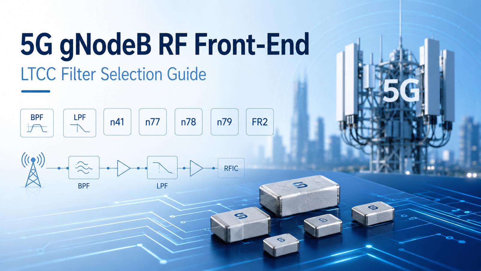
This guide helps RF engineers select LTCC BPF and LPF solutions for 5G gNodeB RF front-end applications, including Massive MIMO AAUs, RRUs / O-RAN RUs, small cells, and 5G private network equipment.
Key Selection Focus
- Target frequency bands: n41, n77/n78, n79, and FR2 26–29 GHz
- BPF selection: RF pre-selection, band selection, and out-of-band interference suppression
- LPF selection: PA output harmonic suppression, spurious rejection, anti-aliasing, and reconstruction filtering
- Key parameters: insertion loss, stopband rejection, VSWR, package size, power handling, and PCB layout
StaronTec Support & Supply Chain Resilience
With in-house ceramic powders, Green Tape, LTCC co-firing processes, and RF testing capabilities, StaronTec ensures stable batch-to-batch consistency and long-term supply support. We also support both standard model selection and custom LTCC filter development for specific RF front-end requirements.
Part 1: Core LTCC Filter Selection Guide for 5G gNodeB
1. Recommended Candidate Models Quick Selection Table
| NR Band / Frequency | Recommended BPF Models | Recommended LPF Models | Application Focus |
|---|---|---|---|
| n1 / n2 / 2 GHz NR / LTE Refarming | FBFCN-1945 | FLFCN-1200 | LTE-to-NR refarming / network upgrade |
| n41 / 2.6 GHz | FBFCN-2491 / FBFCN-2555 | FLFCW-272 / FLFCN-2750 | Macro sites / indoor coverage |
| n78 / C-Band | FBFCN-3600 / FBFCV-3641 | FLFCG-3800 | Mainstream C-Band RU, RRU, and small cells |
| n77 / Wide C-Band | FBFCN-3491 / FBFCN-3600 / FBFCN-3700 / FBFCV-4085 | FLFCG-4400 | Wide C-Band platform / global band coverage |
| n79 / 4.4–5.0 GHz | FBFCN-4800 / FBFHK-4951 / FBFHKI-4951 | FLFCN-5000 | Indoor hotspot / private network |
| FR2 / 26–29 GHz | FBFCQ-2602 / FBFHK-2582 / FBFCQ-2802 / FBFHK-2802 / FBFCQ-2872 / FBFCV-2792 | FLFCN-2752 / FLFCN-2852 / FLFCN-2952 | FR2 mmWave front-end evaluation |
| Wideband / Platform Evaluation | FBFCV-3350 / FBFCV-4085 | FLFCG-4400 / FLFCN-5000 | Prototype validation / multi-band platform evaluation |
Note: Models listed above are for preliminary reference. Final selection should be confirmed according to actual RF, power, package, and PCB layout requirements.
2. 5G gNodeB LTCC BPF Selection Guide
Recommended for use as RF preselectors / band-selection filters in 5G gNodeB Tx/Rx front ends, primarily for target band selection, out-of-band interference suppression, and receive-chain front-end protection.
| Model | Type | Center Freq. (MHz) |
Passband (MHz) |
IL(dB) @ 25°C |
VSWR Typ./Max |
Stopband Summary | Package | Max Power (W) |
Typical Positioning |
|---|---|---|---|---|---|---|---|---|---|
| FBFCN-1945 | BPF | 1945 | 1850–2040 | 3 | 2.5 Max | DC–1500 MHz @ 20 dB; 3600–5700 MHz @ 25 dB | FV1206 | 1.5 | 2 GHz Refarming |
| FBFCN-2491 | BPF | 2491 | 1950–3190 | 3 | 1.43 | DC–1440 MHz @ ≥20 dB; 4500–10000 MHz @ ≥20 dB | FV1206-4 | 1 | 2–3 GHz Wideband |
| FBFCN-2555 | BPF | 2555 | 2500–2610 | 7 | 1.6 | DC–1970 MHz @ ≥20 dB; 2000 MHz @ 30 dB; 3200 MHz @ ≥20 dB; 3250–5500 MHz @ 30 dB | FV1206-1 | 1.5 | n41 Sub-Band |
| FBFCN-3491 | BPF | 3489 | 2790–4370 | 3 | 1.67 | DC–2150 MHz @ ≥18 dB; 5950–7200 MHz @ ≥20 dB; 7200–10000 MHz @ ≥15 dB | FV1206-7 | 1 | Wide C-Band |
| FBFCN-3600 | BPF | 3600 | 3300–3900 | 1.8 | 1.3 | DC–1850 MHz @ ≥20 dB; 5000–8000 MHz @ ≥20 dB | FV1206 | 1.5 | n78 / C-Band |
| FBFCV-3641 | BPF | 3636 | 3400–3850 | 3.5 | 1.7 | DC–2670 MHz @ ≥26 dB; 2930 MHz @ 20 dB; 4650 MHz @ 20 dB; 5350–9600 MHz @ ≥30 dB | JV1210C-2 | 0.5 | Compact C-Band |
| FBFCN-3700 | BPF | 3700 | 3000–4600 | 3.5 | 2.26 | DC–2100 MHz @ ≥21 dB; 5600–8000 MHz @ 24 dB | FV1206-4 | 2.5 | Wide C-Band |
| FBFCN-4100 | BPF | 4100 | 3700–4500 | 2 | 1.5 | DC–2200 MHz @ ≥20 dB; 6000–9000 MHz @ 22 dB | FV1206 | 1.5 | Upper C-Band |
| FBFCN-4800 | BPF | 4800 | 4400–5200 | 2 | 1.7 | DC–1800 MHz @ ≥25 dB; 7500–12000 MHz @ 25 dB | FV1206 | 1.5 | n79 Band Selection |
| FBFHK-4951 | BPF | 4800 | 4300–5300 | 4.5 | 1.57 | 100–2800 MHz @ ≥70 dB; 6700–12300 MHz @ 73 dB | NM1812C-3 | 1 | n79 High Rejection |
| FBFHKI-4951 | BPF | 4800 | 4300–5300 | 4.5 | 1.57 | 100–2800 MHz @ ≥62 dB; 6700–10000 MHz @ 63 dB; 10000–12300 MHz @ 60 dB | NM3237 | 1 | n79 High Rejection / Larger Pkg |
| FBFCV-3350 | BPF | 3350 | 2570–4130 | 3.5 | 2.3 | DC–1900 MHz @ ≥14 dB; 2065 MHz @ 17 dB; 5140–8000 MHz @ 20 dB | JV1210C | 4 | FR1 Wideband Platform |
| FBFCV-4085 | BPF | 4085 | 3130–5040 | 4 | 2.1 | DC–2520 MHz @ ≥15 dB; 6260 MHz @ 17 dB; 6380–8000 MHz @ ≥15 dB; 8000–11000 MHz @ 14 dB | JV1210C | 5 | Upper-FR1 Wideband |
| FBFCQ-2602 | BPF | 26200 | 25000–27500 | 2.8 Max | 1.57 | 100–18000 MHz @ ≥33 dB; 18000–21700 MHz @ ≥25 dB; 31000–37000 MHz @ ≥25 dB; 37000–45000 MHz @ ≥33 dB; 45000–50000 MHz @ ≥26 dB | NL1008C-6 | 1 | FR2 26 GHz |
| FBFHK-2582 | BPF | 25800 | 24250–27500 | 4.5 Max | 1.92 | DC–9000 MHz @ ≥45 dB; 9000–21000 MHz @ ≥34 dB; 21000–21700 MHz @ 40 dB; 29430–33000 MHz @ 30 dB; 33000–35400 MHz @ ≥21 dB; 35400–46000 MHz @ 25 dB | NM1812C-2 | 1 | FR2 n258 |
| FBFCQ-2802 | BPF | 28400 | 27500–29500 | 3.4 Max | 1.57 | 100–20000 MHz @ ≥30 dB; 20000–24200 MHz @ 36 dB;32500–38000 MHz @ 34 dB; 38000–48000 MHz @ 40 dB; 48000–53000 MHz @ 34 dB | NL1008C-6 | 1 | FR2 28 GHz |
| FBFHK-2802 | BPF | 28000 | 26500–29500 | 4.5 Max | 1.92 | DC–14000 MHz @ ≥45 dB; 14000–20000 MHz @ ≥39 dB; 20000–23390 MHz @ ≥30 dB; 23390–24500 MHz @ 25 dB; 32000–32700 MHz @ 33 dB; 32700–37000 MHz @ ≥25 dB; 37000–40000 MHz @ ≥31 dB; 40000–44000 MHz @ 40 dB | NM1812C-2 | 1 | FR2 28 GHz High Rejection |
| FBFCQ-2872 | BPF | 28700 | 27500–30000 | 3 | 1.67 | 100–18000 MHz @ ≥30 dB; 18000–22200 MHz @ ≥22 dB; 35300–38000 MHz @ ≥20 dB; 38000–55000 MHz @ ≥27 dB | NL1008C-7 | 1 | FR2 n257 / n261 |
| FBFCV-2792 | BPF | 27925 | 27500–28350 | 3 | 1.78 | 100–21000 MHz @ ≥35 dB; 21000–25500 MHz @ 26 dB; 31000–35000 MHz @ 22 dB; 35000–45000 MHz @ 12 dB | JV1210C | 1 | FR2 n261 |
3. Detailed LTCC LPF Selection Table for 5G gNodeB
Recommended for use at PA output stages, mixer input/output interfaces, and ADC / DAC signal paths, primarily for harmonic suppression, spurious rejection, ADC anti-aliasing, and DAC reconstruction filtering.
| Model | Type | Passband (MHz) |
3dB Cutoff Typ. (MHz) |
IL(dB) @ 25°C |
VSWR Typ./Max |
Stopband Summary | Package | Max Power |
Target Band/ Typical Application |
|---|---|---|---|---|---|---|---|---|---|
| FLFCN-1200 | LPF | DC–1200 | 1530 | 1 | 1.5 | 1865 MHz @ ≥20 dB; 2000–5000 MHz @ 25 dB; 6200 MHz @ 20 dB | FV1206 | 10 | Sub-1.2 GHz/Low-band NR/LTE RF/IF chain; harmonic and spurious suppression |
| FLFCW-272 | LPF | DC–2690 | 3200 | 1.2 @ DC–2300 MHz; 0.8 @ 2300–2690 MHz | 1.6 | 4400 MHz @ 20 dB; 4800–5400 MHz @ 30 dB; 10000 MHz @ 20 dB | JC0603C | 3 | n41 2.6 GHz/Compact RF/IF LPF near converter; RU/small-cell layouts |
| FLFCN-2750/ 2750D |
LPF | DC–2750 | 3230 | 1 | 1.5 | 4000 MHz @ ≥20 dB; 4100–6800 MHz @ 30 dB; 8400 MHz @ 20 dB | FV1206 | 10 | n41 2.6 GHz/RF/IF LPF with guard margin; RU/RRH/small-cell RF chains |
| FLFCG-3800 | LPF | DC–3900 | 4700 | 1.8 | 1.5 | 5800–6200 MHz @ ≥20 dB; 6200–8400 MHz @ 42 dB; 8400–12000 MHz @ 30 dB; 12000–18000 MHz @ 20 dB | GE0805C-2 | 4.5 | n78 C-Band/RF/IF LPF or converter-adjacent LPF for RU, O-RAN radio and small-cell RF chains |
| FLFCG-4400 | LPF | DC–4400 | 5200 | 2.1 | 1.78 | 6200–6700 MHz @ ≥20 dB; 6700–8800 MHz @ 45 dB; 8800–12200 MHz @ 33 dB; 12200–18000 MHz @ 20 dB | GE0805C-2 | 4.5 | n77 Upper C-Band/RF/IF LPF for RU/O-RAN radio front-end; harmonic and spurious suppression |
| FLFCN-5000 | LPF | DC–5000 | 5610 | 1 | 1.5 | 6850 MHz @ ≥20 dB; 7050 MHz @ 30 dB; 18000 MHz @ 20 dB | FV1206 | 9 | n79 Upper FR1/LPF for RU/small-cell front-end; upper-FR1 spurious and harmonic suppression |
| FLFCN-6000 | LPF | DC–6000 | 6680 | 1.2 | 1.5 | 8500 MHz @ ≥20 dB; 8700–10500 MHz @ 35 dB; 18000 MHz @ 20 dB | FV1206 | 9 | 5–6 GHz Wideband/Extension and test platforms; RF evaluation boards, test fixtures and filtering |
| FLFCW-6000 | LPF | DC–6000 | 6800 | 2.1 | 1.5 | 8200–9000 MHz @ ≥20 dB; 9000–14000 MHz @ 42 dB; 14000–18000 MHz @ 35 dB; 18000–26500 MHz @ 15 dB | JC0603C-1 | 2.5 | 5–6 GHz Wideband/Compact extension and test platforms; converter-adjacent filtering and chain cleanup |
| FLFCN-2752 | LPF | DC–27500 | 29500 | 1.0 @ DC–17000 MHz; 1.8 @ 17000–25500 MHz; 1.5 typ @ 25500–27500 MHz | 1.67 | 34500–39000 MHz @ ≥19 dB; 39000–45000 MHz @ 29 dB; 45000–46000 MHz @ 42 dB | FV1206-11 | 1 | FR2 n258, 24.25–27.5 GHz/mmWave front-end module LPF for RF-chain spurious suppression |
| FLFCN-2852 | LPF | DC–28500 | 30300 | 1.1 @ DC–18000 MHz; 2.8 @ 18000–27000 MHz; 2.1 typ @ 27000–28500 MHz | 1.67 | 35500–40000 MHz @ ≥17 dB; 40000–47000 MHz @ 35 dB | FV1206-11 | 1 | FR2 n261, 27.5–28.35 GHz/28 GHz mmWave front-end or phased-array module LPF |
| FLFCN-2952 | LPF | DC–29500 | 31000 | 1.2 @ DC–18000 MHz; 2.1 @ 18000–28000 MHz; 1.4 typ @ 28000–29500 MHz | 1.67 | 36000–39000 MHz @ ≥20 dB; 39000–41000 MHz @ 33 dB; 41000–48000 MHz @ 42 dB | FV1206-11 | 1 | FR2 n257, 26.5–29.5 GHz/Wideband 28 GHz mmWave front-end LPF for RF-chain spurious suppression |
Note: Models listed above are for preliminary reference. Final selection should be confirmed based on RF performance, power / thermal limits, linearity, package transition, and PCB layout requirements.
Part 2: Typical Positioning and Applications of BPFs and LPFs in 5G gNodeB RF Chains
4. Functional Boundaries Between BPFs and LPFs
In 5G gNodeB RF front ends, BPFs and LPFs are not interchangeable. They serve distinct roles at different stages of the RF chain. Whether a design requires both BPFs and LPFs should be determined based on system spectrum requirements, PA output harmonics, blocker conditions, insertion loss budget, power rating, and PCB layout constraints.
BPF: RF Preselection and Band Selection
Typical Positioning: After the antenna switch, before the LNA, around mixer stages, or at band-selection points in the transmit chain.
Key Selection Factors: Passband coverage, insertion loss, VSWR, adjacent stopband rejection, and rejection of specified out-of-band blockers. When a BPF is placed before the LNA, its insertion loss directly impacts the receive-chain NF budget and should be balanced against stopband rejection performance.
LPF: Harmonic, Spurious, Anti-Aliasing, and Reconstruction Filtering
Typical Positioning: At the PA output stage, after the DAC, before the ADC, or around mixer stages.
Key Selection Factors: Cutoff frequency, passband insertion loss, 2nd- and 3rd-harmonic rejection, power handling capability, and package size. When an LPF is placed at the PA output, output power, peak power, temperature rise, and linearity requirements should also be validated.
5. Tx Chain: Band Selection and High-Frequency Harmonic Control
In the transmit chain, BPFs are mainly used for target band selection and for limiting out-of-band noise, adjacent-channel spurious signals, or unwanted frequency components from entering the downstream amplification stages. LPFs can be used after the DAC for reconstruction filtering, and also at the PA output for high-frequency harmonic and broadband spurious suppression.
A simplified Tx-chain signal flow is shown below:
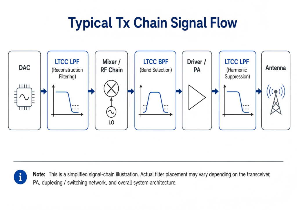
PA Output Harmonic Control
After the RF signal passes through the Driver / PA, the nonlinear behavior of active devices typically generates second-, third-, and higher-order harmonics. Taking a C-Band 3.3–3.9 GHz transmit chain as an example, the typical harmonic distribution is shown below:
| Operating Band | 2nd Harmonic Range | 3rd Harmonic Range |
|---|---|---|
| 3.3–3.9 GHz | 6.6–7.8 GHz | 9.9–11.7 GHz |
Since PA-output harmonics are generated after the amplification stage, a BPF placed before the PA cannot suppress harmonics generated at the PA output. Even when a BPF is already integrated into the RF chain, its far-out high-frequency stopband may not fully meet the PA-output harmonic suppression requirements. Therefore, evaluating an LPF with suitable stopband rejection at the PA output, such as FLFCG-3800, is a common complementary design approach for C-Band transmit chains.
Implementation Considerations
At the system level, the following key parameters should be cross-validated during component selection:
- PA output power and peak power
- Thermal conditions and power handling capability
- IMD3 linearity requirements
- System-level transmit spurious emissions limits / targets
6. Rx Chain: Uplink Signal Preselection and LNA Protection
Compared with the Tx chain, the base station Rx chain must process weak uplink signals from UEs while also potentially encountering strong out-of-band interference from adjacent base stations, co-site coexistence systems, Wi-Fi, industrial wireless equipment, or other sources. These interference signals are collectively referred to as out-of-band blockers.
Typical Rx Chain Signal Flow:
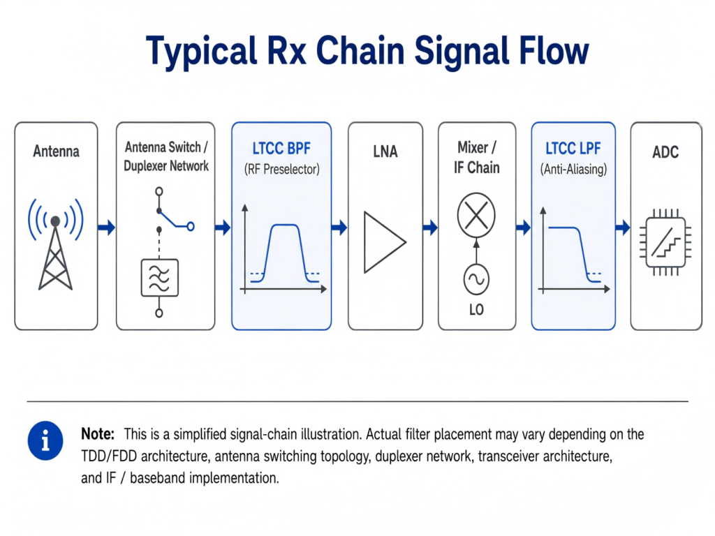
If out-of-band blockers enter the LNA input directly without preselection, they can cause LNA gain compression, receiver blocking, or third-order intermodulation distortion (IMD3). Therefore, an LTCC BPF with low insertion loss and sufficient out-of-band rejection can be placed between the antenna switch / duplexing network and the LNA input to serve as an RF preselector. This helps attenuate out-of-band blockers and reduces the risk of interference reaching the LNA. For example, FBFCN-3600 can be evaluated as a candidate preselector filter for n78 (C-Band) receive front ends.
Implementation Considerations
The core trade-off in Rx front-end BPF selection focuses on two key aspects:
Interference Mitigation: The BPF must provide sufficient out-of-band rejection to reduce the risk of LNA performance degradation caused by blockers.
Noise Performance: Since the BPF is placed before the LNA input, its insertion loss directly contributes to the receive-chain noise figure (NF) budget.
Therefore, Rx front-end BPF selection requires a comprehensive balance among low insertion loss, stopband rejection, VSWR, package size, and specified blocker rejection requirements.
7. Key Selection Considerations for Typical 5G gNodeB Equipment Scenarios
| Equipment / Scenario | Key Selection Considerations |
|---|---|
| Massive MIMO AAU | Low insertion loss, compact package, power handling, temperature stability, and batch-to-batch consistency |
| RRU / O-RAN RU | Target frequency band, stopband rejection, VSWR, power rating, and wide-temperature stability |
| Small Cell | Compact package, standard model availability, cost, lead time, and rapid design-in |
| 5G Private Network Equipment | Band flexibility, customization capability, power rating, environmental conditions, and certification requirements |
| FR2 mmWave Front End | Passband insertion loss, package transition, PCB layout, S-parameters, and thermal management |
8. Key Parameters for Selection Verification
| Key Parameter | Selection Rationale |
|---|---|
| Passband | Confirms coverage of the target operating frequency band and evaluates band-edge margin. |
| Insertion Loss (IL) | Impacts link budget. Rx front-end IL directly contributes to the NF budget, while Tx-chain IL affects output power and efficiency. |
| Out-of-Band Rejection | Evaluates suppression capability for blockers, adjacent bands, harmonics, or broadband spurious emissions; rejection at specified frequencies should be prioritized. |
| VSWR / Return Loss | Affects impedance matching, signal reflection, and matching margin between stages. |
| Power Handling | For PA output stages or large-signal paths, continuous-wave (CW) power, peak power, temperature rise, and linearity should be verified. |
| Package / Layout | Impacts PCB footprint, routing space, package transition, channel-to-channel consistency, and manufacturability. |
Part 3: Standard Products, Customization Capabilities, and Inquiry Information
9. StaronTec Standard Models, Customization Support, and Complementary Passive Components
StaronTec offers standard LTCC BPF/LPF models designed for 5G RF front-end applications, with custom solution evaluation available based on specific project requirements, including frequency bands, package size, and RF performance.
Our standard models support rapid component selection, prototype validation, and early-stage RF chain evaluation. Engineers can shortlist candidate models based on the target frequency band, passband range, insertion loss, stopband rejection, VSWR, package size, and power handling.
Customization Support
When standard models cannot meet project-specific requirements for operating frequency bands, bandwidth, stopband rejection, insertion loss targets, power rating, or SMD package size, StaronTec can evaluate customized LTCC filter solutions. Project specifications are welcome, and we can assist with standard model recommendations or custom feasibility assessment.
Material and Process Capabilities
StaronTec has end-to-end in-house R&D and manufacturing capabilities covering ceramic powders, green tape, multilayer LTCC co-firing processes, and RF testing. This vertical integration supports engineering communication across standard model selection, custom evaluation, and volume production.
By leveraging these in-house material and process capabilities, we can flexibly tune key parameters during custom development and efficiently develop an optimized solution that balances frequency, size, insertion loss, stopband rejection, and package requirements. This also helps support batch-to-batch consistency and long-term supply stability.
Complementary RF Passive Component Support
In addition to LTCC filters, StaronTec supports 5G gNodeB RF front-end projects with complementary RF passive components, including baluns, couplers, and power dividers.
These components are suitable for high-density RF front-end modules and Massive MIMO multi-channel architectures. They support balanced-to-unbalanced conversion, signal distribution, power sampling, test-point monitoring, and module-level integration.
For projects that need to evaluate filters together with other RF passive components, StaronTec can help engineers coordinate specifications, sample requirements, and candidate part selection. This helps reduce multi-vendor communication, sample coordination, and early-stage validation effort.
10. Selection Information and Technical Support
If you are working on RF front-end design and component selection for 5G gNodeBs, RU/RRUs, AAUs, Massive MIMO systems, O-RAN RUs, Small Cells, or 5G private network equipment, you may provide the following project parameters to StaronTec. This helps us quickly evaluate suitable standard LTCC BPF/LPF models or assess the feasibility of a custom solution.
Recommended information includes:
Frequency Requirements & Signal Chain Placement: target operating frequency bands, passband range, bandwidth or cutoff frequency requirements, and the component’s position in the RF chain, such as the Rx front end, pre-LNA or inter-stage positions, post-PA stage, or specific harmonic or spurious suppression nodes.
Core RF Specifications: target insertion loss, return loss / VSWR, specified stopband frequencies, and out-of-band rejection requirements.
Physical & Environmental Parameters: power handling, target SMD package size, PCB footprint, and operating temperature range.
Current Project Stage: early-stage RF chain evaluation, prototype verification, mass production phase-in, replacement part selection, or custom development.
Whether for standard part screening or custom development, you are welcome to share the above project specifications. StaronTec can assist in evaluating suitable LTCC BPF/LPF models and provide related datasheets, S-parameter files (.s2p) for circuit simulation, evaluation boards (EVBs), or engineering samples.